GCP - VPC Virtual Private Cloud
- GCP - Virtual Private Cloud
GCP - Virtual Private Cloud
Virtual Private Cloud
Virtual Private Cloud (VPC)
provides networking functionality to Compute Engine virtual machine (VM) instances, Google Kubernetes Engine (GKE) clusters, and the App Engine flexible environment.
VPC provides networking for the cloud-based resources and services that is global, scalable, and flexible.
Offers built-in Internal TCP/UDP Load Balancing and proxy systems for Internal HTTP(S) Load Balancing.
Connects to on-premises networks using Cloud VPN tunnels and Cloud Interconnect attachments.
Distributes traffic from Google Cloud external load balancers to backends.
- define the own VPC inside the GCP project, or choose the default VPC.
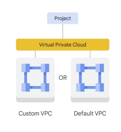
Projects can contain multiple VPC networks.
Unless you with an organizational policy that prohibits it, new projects start with a default network (an auto mode VPC network) that has one subnetwork (subnet) in each region.
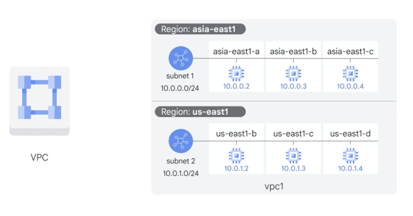
A VPC network is a global resource that
consists of a list of regional virtual subnetworks (subnets) in data centers, all connected by a global wide area network.VPC networks are logically isolated from each other in Google Cloud.
- VPC networks connect the Google Cloud platform resources to each other and to the internet.
- segment the networks,
- use firewall rules to restrict access to instances,
- and create static routes to forward traffic to specific destinations.


Specifications
- Networks are global; subnets are regional
- VPC networks, associated routes and firewall rules have global scope.
- define the own network layout with global scope.
- VPC can have subnets in any GCP region worldwide
- They are not associated with any particular region or zone.
- VPC subnets have regional scope.
- Each subnet defines a range of IP addresses.
- subnet can span the zones that make up a region.
- can have resources in different zones on the same subnet.
- solutions can incorporate fault tolerance without complicating the network topology.
- example
- the VPC has one network.
- it has one subnet defined in GCP us-east1 region.
- it has two Compute Engine VMs attached to it.
- They’re neighbors on the same subnet even though they are in different zones.
- solutions that are resilient but still have simple network layouts.
- VPC networks, associated routes and firewall rules have global scope.
- Traffic to and from instances can be controlled with network firewall rules.
- Rules are implemented on the VMs themselves, so traffic can only be controlled and logged as it leaves or arrives at a VM.
- can dynamically increase the size of a subnet in a custom network by expanding the range of IP addresses.
- Doing that doesn’t affect already configured VMs.
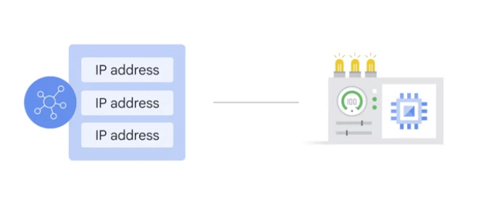
Resources within a VPC network can communicate with one another by using internal IPv4 addresses, subject to applicable network firewall rules.
- VPC networks only support IPv4 unicast traffic.
- do not support broadcast, multicast, or IPv6 traffic within the network;
- VMs in the VPC network can only send to IPv4 destinations and only receive traffic from IPv4 sources.
- However, it is possible to create an IPv6 address for a global load balancer.
Instances with internal IP addresses can communicate with Google APIs and services.
Network administration can be secured by using Identity and Access Management (IAM) roles.
- An organization can use Shared VPC to keep a VPC network in a common host project.
- Authorized IAM members from other projects in the same organization can create resources that use subnets of the Shared VPC network.
VPC networks can be connected to other VPC networks in different projects or organizations by using VPC Network Peering.
VPC networks can be securely connected in hybrid environments by using Cloud VPN or Cloud Interconnect.
- VPC networks support GRE traffic, including traffic on Cloud VPN and Cloud Interconnect.
- VPC networks do not support GRE for Cloud NAT or for forwarding rules for load balancing and protocol forwarding.
- Support for GRE allows you to terminate GRE traffic on a VM from the internet (external IP address) and Cloud VPN or Cloud Interconnect (internal IP address).
- The decapsulated traffic can then be forwarded to a reachable destination.
- GRE enables you to use services such as Secure Access Service Edge (SASE) and SD-WAN.
- Note: GRE support for VPN and Interconnect has been tested only with GRE version 0. Additionally, support for GRE traffic does not include support from Google Cloud for troubleshooting the overlay network.
Default network
Unless disable it, each new project starts with a default network.
- The default network is an auto mode VPC network with pre-populated firewall rules.
disable the creation of default networks by creating an organization policy with the compute.skipDefaultNetworkCreation constraint.
- Projects that inherit this policy won’t have a default network.
subnet
Each VPC network consists of one or more useful IP range partitions called subnets.
- Each subnet is associated with a region
- VPC subnets can span the zones that make up a region
- VPC networks do not have any IP address ranges associated with them.
- can create more than one subnet per region.
- IP ranges are defined for the subnets.
A network must have at least one subnet before you can use it.
- Auto mode VPC networks
- create subnets in each region automatically.
- Custom mode VPC networks
- start with no subnets, giving full control over subnet creation.
creating an instance
- involves selecting a zone, a network, and a subnet. The subnets available for selection are restricted to those in the selected region. Google Cloud assigns the instance an IP address from the range of available addresses in the subnet.
creating a managed instance group
- involves selecting a zone or region, depending on the group type, and an instance template. The instance templates available for selection are restricted to those whose defined subnets are in the same region selected for the managed instance group.
creating an instance template
- Instance templates are global resources
- involves selecting a network and a subnet.
- If you select an auto mode VPC network, you can choose to use auto subnets to defer subnet selection to one that is available in the selected region of any managed instance group that would use the template. Auto mode VPC networks have a subnet in every region by definition.
creating a Kubernetes container cluster
- involves selecting a zone or region (depending on the cluster type), a network, and a subnet. The subnets available for selection are restricted to those in the selected region.
Subnet creation mode
switch a VPC network from auto mode to custom mode is a one-way conversion;
- custom mode VPC networks cannot be changed to auto mode VPC networks.
custom mode VPC network
- no subnets are automatically created.
- provides complete control over its subnets and IP ranges.
- decide which subnets to create in regions by using IP ranges that specify.
auto mode VPC network
- one subnet from each region is automatically created within it.
- These automatically created subnets use a set of predefined IP ranges that fit within the
10.128.0.0/9CIDR block. - As new Google Cloud regions become available, new subnets in those regions are automatically added to auto mode VPC networks by using an IP range from that block.
- In addition to the automatically created subnets, you can add more subnets manually to auto mode VPC networks in regions that you choose by using IP ranges outside of
10.128.0.0/9
consideration
Auto mode VPC networks
- easy to set up and use
- well suited for use cases with these attributes:
- subnets automatically created in each region is useful.
- predefined IP ranges of the subnets do not overlap with IP ranges that you would use for different purposes (for example, Cloud VPN connections to on-premises resources).
custom mode VPC networks
- more flexible and are better suited to production.
- The following attributes highlight use cases where custom mode VPC networks are recommended or required:
- one subnet automatically created in each region isn’t necessary.
- new subnets automatically created as new regions become available could overlap with IP addresses used by manually created subnets or static routes, or could interfere with the overall network planning.
- You need complete control over the subnets created in the VPC network, including regions and IP address ranges used.
- You plan to connect VPC networks by using VPC Network Peering or Cloud VPN. Because the subnets of every auto mode VPC network use the same predefined range of IP addresses, you cannot connect auto mode VPC networks to one another.
- Important: Production networks should be planned in advance. We recommend that you use custom mode VPC networks in production.
Subnet ranges
When create a subnet, must define its primary IP address range.
The primary internal addresses for the following resources come from the subnet’s primary range: VM instances, internal load balancers, and internal protocol forwarding.
optionally add secondary IP address ranges to a subnet, which are only used by alias IP ranges. However, you can configure alias IP ranges for instances from the primary or secondary range of a subnet.
Each primary or secondary IP range for all subnets in a VPC network must be a unique valid CIDR block. Refer to the per network limits for the number of secondary IP ranges you can define.
subnets don’t need to form a predefined contiguous CIDR block, but you can do that if desired. For example, auto mode VPC networks do create subnets that fit within a predefined auto mode IP range.
Valid ranges
A subnet’s primary and secondary IP address ranges are regional internal IP addresses.
Valid ranges:
10.0.0.0/8, 172.16.0.0/12, 192.168.0.0/16- Private IP addresses RFC 1918
100.64.0.0/10- Shared address space RFC 6598
192.0.0.0/24- IETF protocol assignments RFC 6890
192.0.2.0/24 (TEST-NET-1), 198.51.100.0/24 (TEST-NET-2), 203.0.113.0/24 (TEST-NET-3)- Documentation RFC 5737
192.88.99.0/24- Pv6 to IPv4 relay (deprecated) RFC 7526
198.18.0.0/15- Benchmark testing RFC 2544
240.0.0.0/4- Reserved for future use (Class E) as noted in RFC 5735 and RFC 1112.
- Some operating systems do not support the use of this range, so verify that the OS supports it before creating subnets that use this range.
Privately used public IP addresses- Includes IP addresses that are not part of the RFC ranges listed in this table and not part of the restricted set.
- use these addresses as subnet ranges, Google Cloud does not announce these routes to the internet and does not route traffic from the internet to them.
- For VPC Network Peering, subnet routes for
public IP addressesare not automatically exchanged. - The subnet routes are automatically exported by default, but peer networks must be explicitly configured to import them in order to use them.
1
2
3
4
5
6
7
8
gcloud compute --project=qwiklabs-gcp-00-cdc530d7d99c \
  firewall-rules create managementnet-allow-icmp-ssh-rdp \
                        --direction=INGRESS \
                        --priority=1000 \
                        --network=managementnet \
                        --action=ALLOW \
                        --rules=tcp:22,tcp:3389,icmp \
                        --source-ranges=0.0.0.0/0
Restricted ranges
Restricted ranges include Google public IP addresses and commonly reserved RFC ranges, These ranges cannot be used for subnet ranges.
Range Description
Public IP addresses for Google APIs and services, including Google Cloud netblocks- https://gstatic.com/ipranges/goog.txt.
199.36.153.4/30 and 199.36.153.8/30- Private Google Access-specific virtual IP addresses
0.0.0.0/8- Current (local) network RFC 1122
127.0.0.0/8- Local host RFC 1122
169.254.0.0/16- Link-local RFC 3927
224.0.0.0/4- Multicast (Class D) RFC 5771
255.255.255.255/32- Limited broadcast destination address RFC 8190 and RFC 919
Reserved IP addresses in a subnet- Every subnet has four reserved IP addresses in its primary IP range .
- There are no reserved IP addresses in the secondary IP ranges .
- Network
- First address in the primary IP range for the subnet
10.1.2.0 in 10.1.2.0/24
- Default gateway
- Second address in the primary IP range for the subnet
10.1.2.1 in 10.1.2.0/24
- Second-to-last address
- Second-to-last address in the primary IP range for the subnet that is reserved by Google Cloud for potential future use
10.1.2.254 in 10.1.2.0/24
- Broadcast
- Last address in the primary IP range for the subnet
10.1.2.255 in 10.1.2.0/24
- Network
Route
Without a VPC network, there are no routes and no firewall rules!
Routes define paths for packets leaving instances (egress traffic).
- Routes tell VM instances and the VPC network how to send traffic from an instance to a destination, either inside the network or outside of Google Cloud.
Routes in Google Cloud are divided into two categories: system-generated and custom .
- Each VPC network comes with some system-generated routes
- to route traffic among its subnets and send traffic from eligible instances to the internet.
- Every new network starts with two types of system-generated routes:
- The default route
- defines a path for traffic to leave the VPC network
- It provides general internet access to VMs that meet the internet access requirements.
- It also provides the typical path for Private Google Access.
- subnet route
- define paths for traffic to reach VMs that use the subnets
- a subnet route is created for each of the IP ranges associated with a subnet.
- Every subnet has at least one subnet route for its primary IP range.
- Additional subnet routes are created for a subnet if you add secondary IP ranges to it.
- You cannot remove subnet routes manually.
- The default route
- create custom static routes to direct some packets to specific destinations.
- static routes that create manually
- dynamic routes maintained automatically by one or more of the Cloud Routers.
Dynamic routing mode
- Each VPC network has an associated dynamic routing mode that controls the behavior of all of its Cloud Routers
- Cloud Routers
- share routes to your VPC network
- learn custom dynamic routes from connected networks when you connect your VPC network to another network by using a
Cloud VPN tunnel that uses dynamic routing, or by usingDedicated / Partner Interconnect.
- Regional dynamic routing is the default.
routes to on-premises resources learned by a given Cloud Router in the VPC networkonly apply to the subnets in the same region as the Cloud Router.- Unless modified by custom advertisements, each Cloud Router only shares the routes to subnets in its region with its on-premises counterpart.
- Global dynamic routing
- changes the behavior of all Cloud Routers in the network such that the
routes to on-premises resources that they learnare available in all subnets in the VPC network, regardless of region. - Unless modified by custom advertisements, each Cloud Router shares routes to all subnets in the VPC network with its on-premises counterpart.
- changes the behavior of all Cloud Routers in the network such that the
The dynamic routing mode can be set when create or modify a VPC network.
- can change the dynamic routing mode from regional to global and vice-versa without restriction.
- Changing the dynamic routing mode has the potential to interrupt traffic within the network or enable or disable routes in unexpected ways. Carefully review the role of each Cloud Router before changing the dynamic routing mode.
routing tables / Forwarding rules
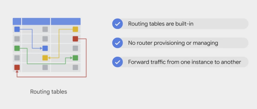
While routes govern traffic leaving an instance, forwarding rules direct traffic to a Google Cloud resource in a VPC network based on IP address, protocol, and port.
- Much like physical networks, VPCs have routing tables.
- forward traffic between instance within the same network.
- forward traffic across sub-networks
- forward traffic between GCP zones without requiring an external IP address.
Destinations for forwarding rules are
target instances,load balancer targets(target proxies, target pools, and backend services), andCloud VPN gateways.- VPCs routing tables are built in,
- don’t have to provision or manage a router.
- don’t have to provision or manage for GCP, a firewall instance.
Firewall
Without a VPC network, there are no routes and no firewall rules!
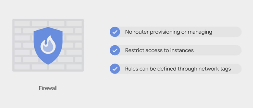
Global distributed firewall
Each VPC network implements a distributed virtual firewall
- Firewall rules apply to both outgoing (egress) and incoming (ingress) traffic in the network.
- Firewall rules control traffic even if it is entirely within the network, including communication among VM instances.
Firewall rules control which packets are allowed to travel to which destinations.
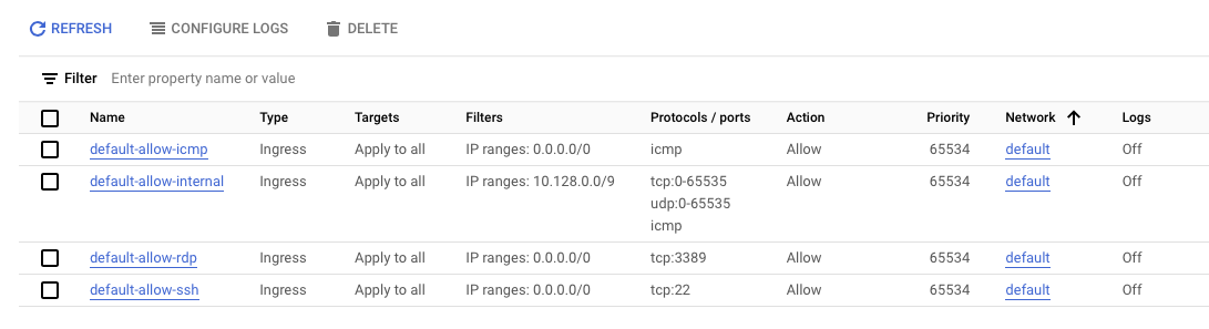
- Every VPC network has two implied firewall rules
- One rule allows most egress traffic,
- and the other denies all ingress traffic.
- cannot delete the implied rules, but can override them
- The
defaultnetwork has additional firewall rules- including the
default-allow-internalrule: permit communication among instances in the network.
- including the
- Google Cloud always blocks some traffic, regardless of firewall rules; for more information, see blocked traffic.
- Every VPC network has two implied firewall rules
firewall example
- default-allow-icmp
- default-allow-rdp
- default-allow-ssh
- default-allow-internal
- These firewall rules allow
- all
ICMP, RDP, and SSHingress traffic from anywhere (0.0.0.0/0) - all
TCP, UDP, and ICMPtraffic within the network (10.128.0.0/9).
- all
Firewall rule with Tag
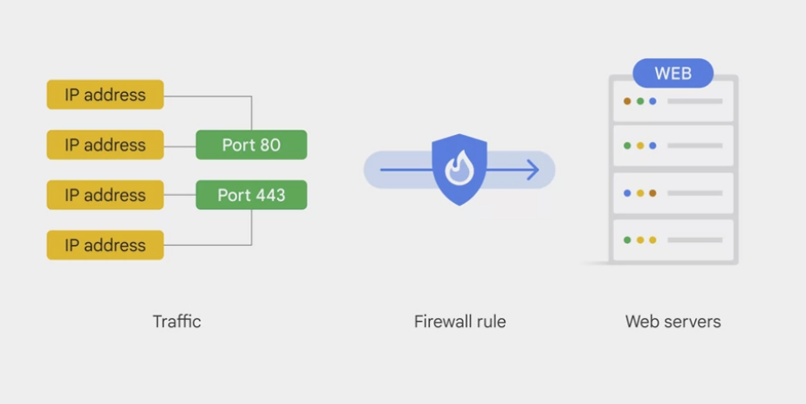
- define firewall rules in terms of metadata tags on Compute Engine instances
- example
- tag all the web servers with say, “web,”
- and write a firewall rule saying that traffic on ports 80 or 443 is allowed into all VMs with the “web” tag, no matter what their IP address happens to be.
DNS
General DNS
- 8.8.8.8
- Google services
- provides a public domain name service to the world.
- DNS is what translates internet host names to addresses.
- Google has a highly developed DNS infrastructure.
- It makes 8.8.8.8 available so that everybody can take advantage of it.
Google Cloud DNS
for the internet host names and addresses of applications build in GCP
to help the world find them
a managed DNS service running on the same infrastructure as Google.
It has low latency and high availability
a cost-effective way to make the applications and services available to the users.
The DNS information you publish is served from redundant locations around the world.
Cloud DNS is also programmable.
- publish and manage millions of DNS zones and records
- using the GCP console, the command line interface or the API.
Google Cloud CDN

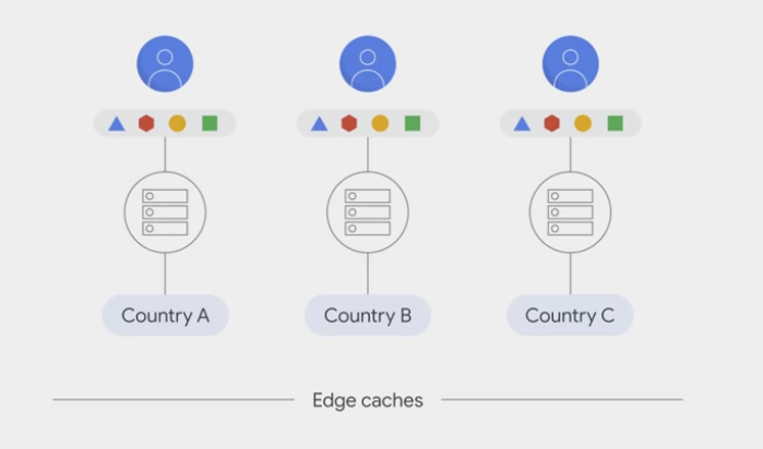
Edge caches
- Google has a global system of edge caches.
- You can use this system to accelerate content delivery in the application
- the customers
- experience lower network latency.
- The origins of the content
- experience reduced load
- and save money too.
- Once you’ve set up HTTPS load balancing, simply enable Cloud CDN with a single checkbox.
- CDN is a part of GCPs,
- CDN interconnect partner program and you can continue to use it.
Interfaces and IP addresses
IP addresses
Google Cloud resources, such as Compute Engine VM instances, forwarding rules, GKE containers, and App Engine, rely on IP addresses to communicate.
Alias IP ranges
For multiple services running on a single VM instance
- can give each service a
different internal IP addressby using alias IP ranges. - The VPC network forwards packets that are destined to a particular service to the corresponding VM.
Network interfaces
Add multiple network interfaces to a VM instance
- each interface resides in a unique VPC network.
- Multiple network interfaces enable a network appliance VM to act as a gateway for securing traffic among different VPC networks or to and from the internet.
Hybrid cloud and VPC connection
Cloud Load Balancing


- a fully distributed, software-defined managed service for all the traffic .
- because the load balancers don't run in VMs, no worry about scaling or managing them.
- put Cloud Load Balancing in front of all the traffic
- HTTP and HTTPS, TCP, UDP and SSL traffic
- basic
- you application presents a single front-end to the world
- users get a single, global anycast IP address
- Traffic goes over the google backbone from the closet point-of-presence to the user
- backend instances in regions around the world.
- provides cross-region load balancing
- including automatic multi-region failover,
- backbone are selected based on load
- Cloud Load Balancing reacts quickly to changes in users, traffic, backend health, network conditions, and other related conditions.
- gently moves traffic in fractions if backends become unhealthy.
- only healthy backends receive reaffic
- no pre-warming is required
different load balancer
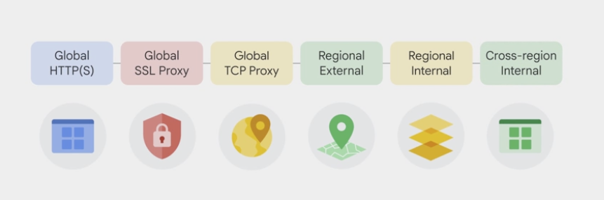
- Global external load balancing
- global HTTPS load balancer
- layer 7 load balancing based on load
- cross regional load balancing for web application
- route different URLs to different back ends
- global SSL proxy load balancer
- layer 4 load balancing of non-HTTPS SSL traffic based on load
- For Secure Sockets Layer traffic that is not HTTP
- Supported on specific port numbers
- only work for TCP and specific port numbers
- global TCP proxy load balancer
- layer 4 load balancing of non-SSL TCP traffic
- If it’s other TCP traffic that does not use Secure Sockets Layer
- Supported on specific port numbers
- only work for TCP and specific port numbers
- global HTTPS load balancer
- Regional external Network Load Balancing
- regional load balancer
- load balancing of any traffic (TCP/UDP) on any port number
- load balance across a GCP region with the regional load balancer
- regional load balancer
- Regional Internal TCP/UDP Load Balancing
- internal load balancer
- load balance traffic inside a VPC / the project
- for traffic
- coming into the Google network from the internet.
- example:
- between the presentation layer and the business logic layer of the application
- TCP traffic on arbitrary port numbers
- UDP traffic
- coming into the Google network from the internet.
- accepts traffic on a GCP internal IP address and load balances it across Compute Engine VMs.
- for the interbal tiers of multi-tier applications
- to load-balance traffic among the back-end VMs that form part of a multi-tier application.
- internal load balancer

Communications and access
Communication within the network
- The system-generated subnet routes define the paths for sending traffic among instances within the network by using
internal IP addresses. - The Firewall
- For one instance to be able to communicate with another, appropriate firewall rules must also be configured because every network has an
implied deny firewall rule for ingress traffic. - Except for the default network, must explicitly create higher priority ingress firewall rules to allow instances to communicate with one another.
- The default network includes several other firewall rules:
- the
default-allow-internal rule: permits instance-to-instance communication within the network. - The default network also comes with
ingress rules allowing protocols such as RDP and SSH. - Rules that come with the default network are also presented as options for you to apply to new auto mode VPC networks that you create by using the Cloud Console.
- the
- For one instance to be able to communicate with another, appropriate firewall rules must also be configured because every network has an
Internet access requirements
The following criteria must be satisfied for an instance to have outgoing internet access:
- default internet gateway route or custom route
- The network must have a valid
default internet gateway route or custom routewhose destination IP range is the most general (0.0.0.0/0). This route defines the path to the internet.
- The network must have a valid
- Firewall rules
- must allow egress traffic from the instance.
- Unless overridden by a higher priority rule, the implied allow rule for egress traffic permits outbound traffic from all instances.
- One of the following must be true:
- The instance must have an
external IP address. be assigned when created or after created. - The instance must be able to use
Cloud NATor aninstance-based proxythat is the target for a static 0.0.0.0/0 route.
- The instance must have an
Communications and access for App Engine
VPC firewall rules apply to resources running in the VPC network, such as Compute Engine VMs.
For App Engine instances, firewall rules work as follows:
- App Engine standard environment:
- Only App Engine firewall rules apply to ingress traffic.
- Because App Engine standard environment instances do not run inside your VPC network, VPC firewall rules do not apply to them.
- App Engine flexible environment:
- Both App Engine and VPC firewall rules apply to ingress traffic.
- Inbound traffic is only permitted if it is allowed by both types of firewall rules.
- For outbound traffic, VPC firewall rules apply.
Traceroute to external IP addresses
- For internal reasons, Google Cloud increases the TTL counter of packets that traverse next hops in Google’s network.
- Tools like
tracerouteandmtrmight provide incomplete results because the TTL doesn’t expire on some of the hops.
Hops that are inside and outside of Google’s network might be hidden in these circumstances:
- When you send packets from Compute Engine instances to external IP addresses, including external IP addresses of other Google Cloud resources or destinations on the internet.
- When you send packets to the external IP address associated with a Compute Engine instance or other Google Cloud resource.
The number of hidden hops varies based on the instance’s Network Service Tiers, region, and other factors. If there are only a few hops, it’s possible for all of them to be hidden. Missing hops from a traceroute or mtr result don’t mean that outbound traffic is dropped.
There is no workaround for this behavior. You must take it into account if you configure third-party monitoring that connects to an external IP address associated with a VM.
Important:
- Probe loss statistics are a component of traceroute tests, but care must be taken when analyzing test results. traceroute and mtr by default utilize ICMP-based probing.
- ICMP probe response generation is typically rate-limited (or disabled) in routers that reside in the network path of your probing and can result in missing probe responses.
- When this behavior occurs, you may see probe loss in intermediate routing hops, but this should not reflect end-to-end performance. If looking for packet loss, the only hop that generally matters is the destination hop.
Egress throughput limits
Network throughput information is available on the Network bandwidth page in the Compute Engine documentation.
Packet size
Information about packet size is in the maximum transmission unit section.
Maximum transmission unit - MTU
The MTU is the size, in bytes, of the largest packet supported by a network layer protocol, including both headers and data.
VPC networks have a default maximum transmission unit (MTU) of 1460 bytes. However, you can configure your VPC networks to have an MTU of 1500 bytes.
- In Google Cloud, you set the MTU for each VPC network, and VM instances that use that network must also be configured to use that MTU for their interfaces.
- The network’s MTU setting is communicated to a VM when that VM requests an IP address using DHCP. DHCP Option 26 contains the network’s MTU.
The MTU impacts both UDP and TCP traffic:
- If a UDP packet is larger than the destination can receive or the MTU on network link on the path to the destination, the packet
- dropped if the
Don't-Fragmentflag is set. an ICMP packet of the typeFragmentation-Neededis sent back to the sender. - (generally) fragmented if the
Don't-Fragmentflag is not set. This fragmentation is done where a mismatch is detected: this could be at an intermediate router or even at the sender itself if a packet is sent that is larger than the MTU.
- dropped if the
- TCP negotiates the maximum segment size (MSS) during connection setup time. Packets are then segmented into the smaller MTU size of both endpoints of the connection.
VMs and MTU settings
Linux VMs based on Google-provided OS images automatically have their interface MTU set to the MTU of the VPC network when they are created.
If a VM has multiple network interfaces, each interface is set to the MTU of the attached network.
If you change the MTU of a VPC that has running VMs, you must stop and then start those VMs to pick up the new MTU. When the VMs start up again, the changed network MTU is communicated to them from DHCP.
Windows VMs do not automatically configure their interfaces to use the VPC network’s MTU when they start. To set Windows VMs based on Google-provided OS images to an MTU of 1500, do the following on each Windows VM:
1
2
3
netsh interface ipv4 show interface
netsh interface ipv4 set interface INTERFACE_INDEX mtu=1500 store=persistent
shutdown /r /t 0
Set-NetIPInterface -InterfaceAlias INTERFACE_NAME -AddressFamily IPv4 -NlMtu 1500
Restart-Computer -Force
Migrating services to a different MTU network
to migrate your services to new VMs in a new network rather than changing the MTU of your existing network. In such a case, you might have a server, such as a database server, that needs to be accessible to all VMs during the migration. If so, the following general approach might help you migrate cleanly:
- Create the new network with the new MTU.
- Create any necessary firewall rules and routes in the new network.
- Create a VM with multiple network interfaces in the old network. One interface connects to the new network using the new MTU and the other connects to the old network using the old MTU.
Configure this new VM as a secondary server for the existing one.
- Fail the primary server over to the secondary one.
- Either Migrate VMs to the new network or create new VMs in the new network.
- If you create new VMs, you can create them from scratch, from an existing image, or by creating a snapshot of the existing VMs and using that to populate the new persistent disks.
- Configure these VMs to use the operational server in that network.
- Migrate traffic to the new VMs.
- If you intend to delete the old network, create a new server in the new network, get it in sync with the existing server, and fail over to it.
- Delete the old server and old network.
Consequences of mismatched MTUs
mismatched MTU: two communicating VM instances that have different MTU settings.
- This can, in a limited number of cases, cause connectivity problems. Specific cases involve the use of instances as routers and the use of Kubernetes inside VMs.
- In most common scenarios, TCP connections established between instances with different MTUs are successful due to the MSS negotiation, where both ends of a connection will agree to use the lower of the two MTUs.
- This applies whether the two VMs are in the same network or peered networks.
MTU differences with Cloud VPN
MTU differences with Cloud Interconnect
Cloud Interconnect can have an
MTU of 1440 or 1500.- If the
communicating VMshave an MTU of 1500 and theInterconnect connectionhas an MTU of 1440- MSS clamping reduces the MTU of TCP connections to 1440 and TCP traffic proceeds.
- MSS clamping does not affect UDP packets
- if the
VPC networkhas an MTU of 1500 and theInterconnect connectionhas an MTU of 1440,- then UDP datagrams with more than 1412 bytes of data (1412 bytes UDP data + 8 byte UDP header + 20 byte IPv4 header = 1440) are dropped.
- In such a case, you can do one of the following:
- Lower the MTU of the attached VPC network to 1460.
- Adjust your application to send smaller UDP packets.
- Create a new Interconnect connection of 1500 bytes
- In such a case, you can do one of the following:
- then UDP datagrams with more than 1412 bytes of data (1412 bytes UDP data + 8 byte UDP header + 20 byte IPv4 header = 1440) are dropped.
Network performance
Latency
The measured inter-region latency for Google Cloud networks can be found in our live dashboard.
The dashboard shows Google Cloud’s
median inter-region latencyandthroughput performance metricsandmethodology to reproducethese results using PerfKit Benchmarker.Google Cloud typically measures round-trip latencies less than 55 μs at the 50th percentile and tail latencies less than 80μs at the 99th percentile between c2-standard-4 VM instances in the same zone.
Google Cloud typically measures round-trip latencies less than 45μs at the 50th percentile and tail latencies less than 60μs at the 99th percentile between c2-standard-4 VM instances in the same low-latency network (“compact” placement policy). Compact placement policy lowers the network latency by ensuring that the VMs are located physically within the same low-latency network.
Methodology: Intra-zone latency is monitored via a blackbox prober that constantly runs netperf TCP_RR benchmark between a pair of c2-types VMs in every zone c2 instances are available. It collects P50 and P99 results for setup with and without compact placement policy. TCP_RR benchmark measures request/response performance by measuring the transaction rate. If your applications require best possible latency, c2 instances are recommended.
Packet loss
Google Cloud tracks cross-region packet loss by regularly measuring round-trip loss between all regions.
- We target the global average of those measurements to be lower than 0.01% .
- Methodology:
- A blackbox vm-to-vm prober monitors the packet loss for every zone pair using pings and aggregates the results into one global loss metric.
- This metric is tracked with a one-day window.
.
Comments powered by Disqus.